
Content:
The Nintendo Wii U, released in 2012, is a home console which is part of the 8th generation of video game consoles. It competed with the Microsoft Xbox One, and the Sony PlayStation 4.
A unique feature of the console is the GamePad, a controller featuring a touchscreen to control games. The GamePad houses a 1500mAh battery, with quoted battery life of between 3 and 5 hours.
Nintendo chose to use a proprietary charging port on the GamePad, requiring the use of a WUP-001 charger. This charger is capable of outputting up to 1.6A at 4.75V.
However, it is possible to charge the GamePad using a USB A-Wii U port charging cable, using 5V rather than the 4.75v of the original power brick.
The included charging dock also includes the proprietary charging port. Here’s how you can convert this charging port to USB C, providing a more universal charging option to the Wii U GamePad, without having to open the pad itself.

Convert a Wii U Dock to USB Type C
Check out our video showing the board in action.

Wii U Dock USB Type C Board
Purchase a pre-built Wii U dock USB type C charging board through our Ko-Fi store.
Inside The Dock
The plastic charging dock is a very simple design.

Remove the 5 tri-wing screws.
Once the five tri-wing screws are removed, the back can be easily lifted away from the main body of the dock.
Inside is a small board holding the charging port, the metal wires that contact with the gamepad charging pads, and the spring mechanism to lift the wires when a gamepad is docked.

Replacing the original board is therefore simple.
New Board
I have designed a very simple board to replace the original. This board features a 16 pin USB C connector – look for one with straight legs.
Also features a section to wire a switch to control the charging state independently of the input power source. I included this option as it is not a good idea to leave a rechargeable device constantly on charge.

If you do not wish to use the switch, the board is a near drop-in replacement for the original. Simply desolder the wires from the original board, and attach them to this board. You will also need to bridge the two points labelled ‘switch’ – without this, the + wire will not be connected.
To fit the USB C port in place of the original, I found it neccesary to sand a small amount from the inner section of the connector housing.

I did not alter the hole in the outside of the dock – it’s a tight fit, but it works fine without modification. As the USB C connector is shorter than the original, there will be a gap below it in the assembled dock.
Updates to the Board
The board photographed above is a slightly older version – the latest board, released 14th March 2022, has added resistor pads on the CC lines to allow the use of fast chargers, and replaced the through holes with pads.
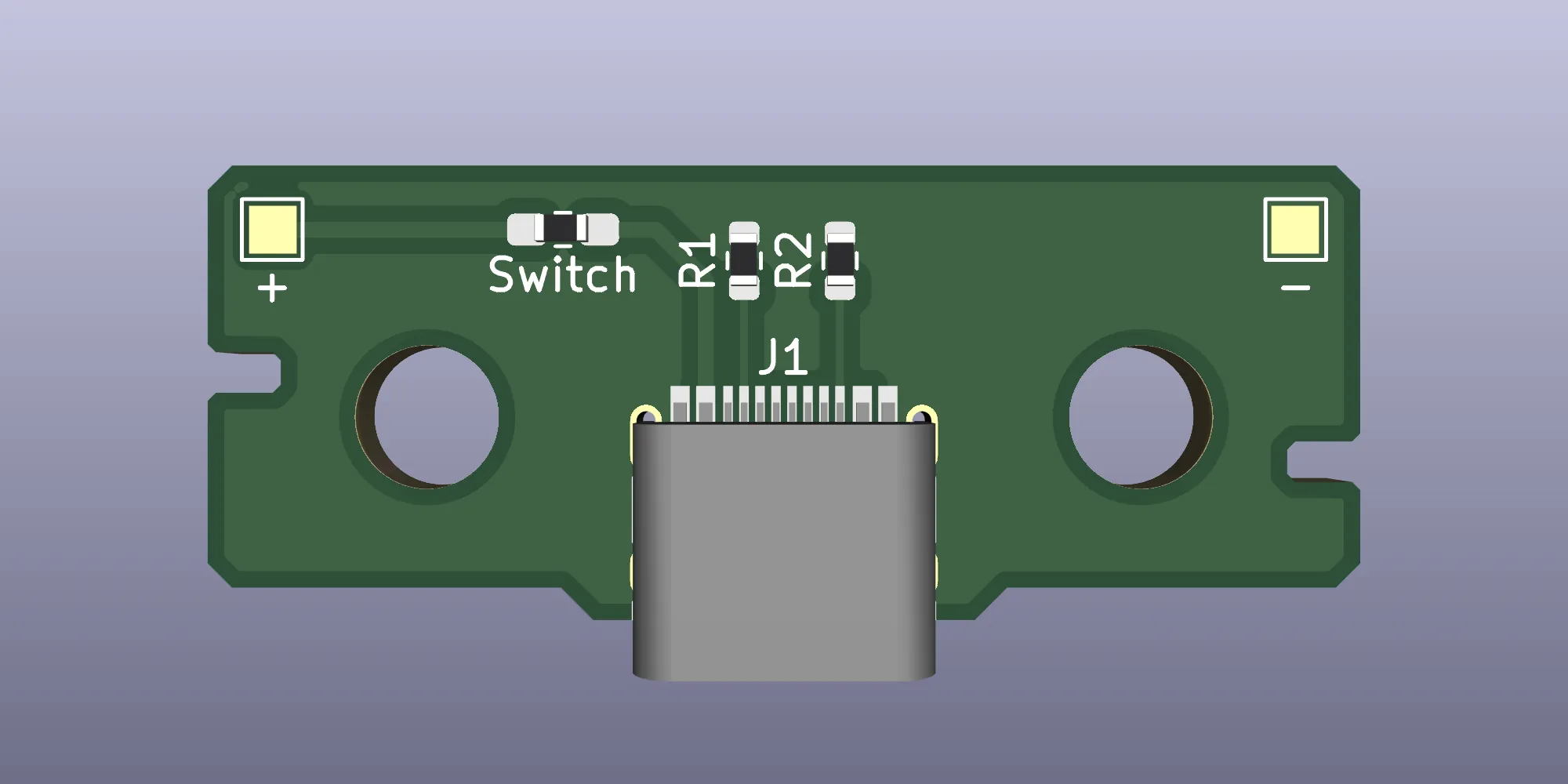
To make use of this, populate R1 and R2 with 5.1kΩ 0603 resistors. Any will do, though I’d suggest sticking to 1% resistors if possible. These are completely optional – the board will work fine without them, but without support for smart chargers.
In addition, the switch solder points have been changed to pads, again with an 0603 layout (albeit with elongated pads to make it easier to solder wires to them). You can bridge these with wire, or a 0Ω 0603 resistor, if you’re not using a switch.
If you want to make your own board, you can order them directly from the shared project on OSH Park using the link below.

Wii U Dock USB Type C PCB
Order a batch of PCBs directly from OSH Park.
The original design files can be found on GitHub, which is linked at the bottom of the post.
Adding A Switch (Optional)
Adding a switch to the dock requires a bit more work. I chose to use a 12mm metal LED-less button. Looking at the dock face-on, I have mounted it to the right-hand side, though it would work just as well on the other side.
The most tricky part is cutting the case to fit the switch in place. As well as making a hole in the outer case, the inner plastic also needs to be trimmed. This could make the rubber support on the top of the dock a little loose, so you might want to add a small amount of hot glue to keep it in position. I chose not to do this, as the support seemed to stay pretty much where it was supposed to be.

Once the switch is fitted, solder one of the switch connectors to one of the ‘switch’ through holes on the board, and solder the other to the other through hole. Polarity doesn’t matter, though if your board has an LED, you will need to make sure the + side is connected to the through hole closest to the USB C port, with the – side connected to the outer through hole. Bear in mind that this board will be carrying 5V, so make sure your switch is designed for 5V usage.

Troubleshooting
There shouldn’t be any issues using this board, as it features no active components. If your Wii U gamepad is not charging, first check that the wires in the dock rise when pushing down on the button in the centre. If they don’t, you will need to check the spring mechanism inside the dock. In my case, I did have to bend the wires slightly outwards, as one side had been squashed down at some point when fitting the switch.
The other thing to check would be that the solder joints are making a good connection, and the polarity is correct. If you have fitted a switch, try temporarily bridging the solder points to ensure the switch is not defective.
Design Files
The original KiCAD files can be found over on Github, along with the Gerber files if you want to order one for yourself.

Wii U Dock USB Type C Board
A replacement board for a Wii U dock, with a USB type C connector.


