

Content:
One of the key benefits of the Qidi X Smart 3 compared to similarly priced competitors is the enclosed print area. While the print chamber is not heated (unlike the X Max 3 and X Plus 3), the enclosed design does help to reduce drafts around prints, allow greater control of printing fumes, and keep the hot end and heated bed away from pets and children.
A disadvantage, though, is that the enclosure will trap heat inside the print chamber, raising the temperature and potentially impacting the quality of the print. This is particularly true of the venerable PLA, which is the most common filament used for printing.
The top of the printer even includes a warning, advising users to remove the top panel, and open the door, to reduce temperatures when printing PLA.
In the usually cool climate of the UK, the printer should still remain cool enough to print PLA with the door closed and top panel in place. It would be useful, though, to be able to monitor the chamber temperature to ensure this is the case.
This can be done cheaply and easily by adding a thermistor to the print chamber. It wont have the greatest precision, but will be more than enough to give a rough idea of the temperature inside the print chamber.
This guide will specifically be adding this functionality to a Qidi X Smart 3, but the same changes can be applied to any printer running Klipper, provided your control board has somewhere you can plug in a thermistor.
Required Part
The only additional part required for this modification is a thermistor. Specifically, we’re using a 100k NTC 3950 thermistor, with a 2-pin JST-XH connector. We managed to get one of these from AliExpress for less than £1.

Installation
WE specifically chose the version with the JST-XH connector, so that we could plug it in to one of the spare connectors on the original motherboard used in the printer. To access this, you will need to turn the printer over, and remove the metal plate covering the board.
We chose to use the TH connector, which has pins labelled PA1 and GND, so PA1 is the pin name that will be used in the config later on. You can use the pinout below to see the layout of the board, and the associated connector names. Note that this is v1.0 of the board – yours might be slightly different.

There is space to feed the thermistor through into the chamber alongside the wires used to connect to the axis motors.
Where you mount the thermistor inside the chamber is up to you, though we would recommend keeping it towards the upper half of the chamber, as this is where the printing will be taking place. It doesn’t matter too much though, because as mentioned previously, we won’t be expecting high levels of accuracy in our temperature readings.
We chose to the mount the end of the thermistor next to the exhaust fan, with the tip bent away from the rear of the chamber. A small amount of hot glue holds the thermistor in place, with the excess wire looped between two of the rear cable mounts.
Software
To enable the temperature sensor, you’ll need to edit the config.cfg file. You should be able to find this in the printer’s web UI. If you’re using Mainsail, you can find it under the Machine section.
Add the following section to the file. It doesn’t matter where you add it, though we decided to put it under the heater_bed section as this section also configures a thermistor.
[temperature_sensor chamber_temp]
sensor_type: NTC 100K MGB18-104F39050L32
sensor_pin: PA1
min_temp: -50
max_temp: 125
Replace the sensor_pin value with the name of the pins you have chosen to use.
Save the file, and reboot the machine for the new config to take effect.
Testing
Once rebooted, you should see a new temperature entry on the dashboard.
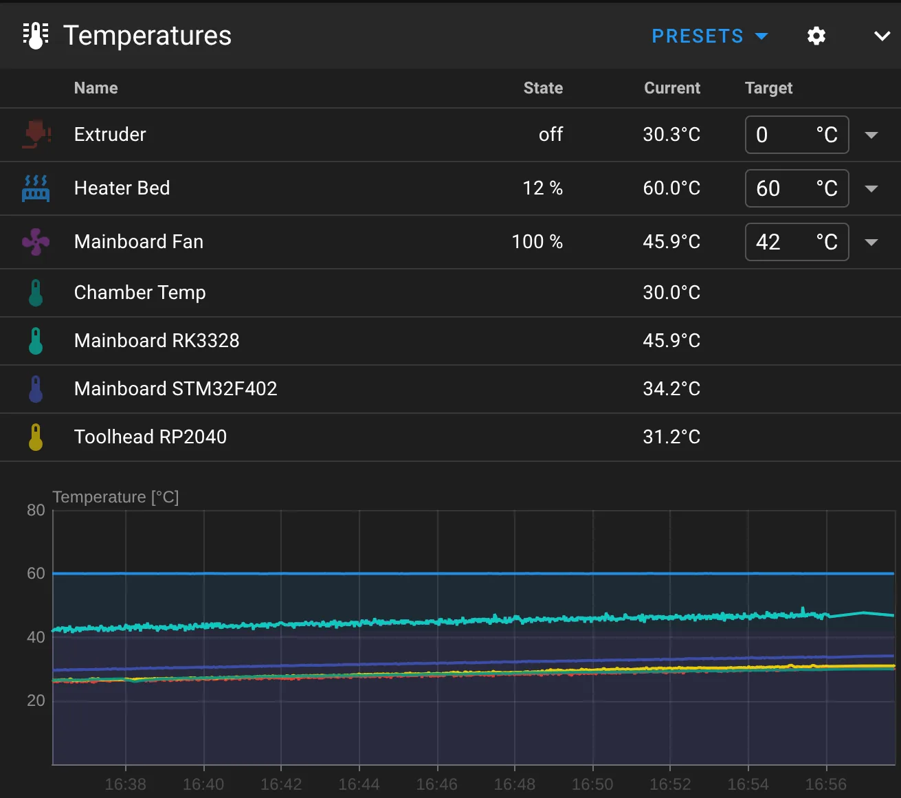
Verify that the value seems sensible, and keep an eye on it when you run a few prints.
That’s all there is to it. You’re now able to keep track of the chamber temperature of your X Smart 3 printer!


