
Content:
Back in 2017, we shared our design for a Lithium-Polymer battery charger. Based on the Adafruit Micro LiPo, the charger added reverse polarity protection, as well as an additional battery connector on the underside, to cater for batteries with a JST-ZH connector.
We have a couple of these chargers, and while they have done the job for the last 9 years, it’s time for an update. Using the old design as a base, we’ve created a new charger which have several advantages over the previous version.
This post will go over the features of the new board, as well as providing instructions for you to make your own.
USB Type C Input
The inclusion of a USB type C input (replacing the Micro USB port on the older design) one of the more obvious changes. PD is supported, though only at 5V (which is more than enough to charge LiPo’s at safe speeds).
A 16-pin type C port is used, along with two 5.1kΩ resistors to enable PD.
Charging Speed Selector
A slide switch has been added to the side of the board, to switch between two charging speeds. Using the resistors listed in the BOM, the switch toggles between 100mA and 500mA charging speeds, as noted on either end of the switch.
This replaces the jumper used in the old design, which required soldering/desoldering to change the speed.
Output Connectors
The board is longer and wider than the original, so there’s now room for both a JST-PH and JST-ZH connector on the top of the board. These can be easily replaced with other JST footprints if you have batteries with other connectors.
On the underside of the board, footprints are included for another set of JST-PH and JST-ZH connectors, this time with the polarity of the connectors reversed. The outputs on this side match the polarity used in PS3/PS4 controllers, which is revered compared to other LiPos. This means the batteries will no longer need to have their wires flipped for charging outside of a controller.
Larger PCB
Depending on your point of view, this might not be an advantage. If you’re soldering by hand, the larger size and slightly more spaced-out components definitely make assembling a board easier, while also improving heat dissipation from the charger IC (which does get hot when charging at 500mA).
Retained Features
As with the previous version of the charger, this charger features two pin headers which can be used to add additional outputs to the board. We find these incredibly useful for testing the voltage of the attached battery, as the through holes do a great job of holding the multi-meter probes in position.
The reverse-polarity protection, status LEDs are retained, as are two of the original four mounting holes. Note that this PCB has a different footprint to the original, so the mounting holes are not compatible.
The base design of both PCBs is the Adafruit Micro LiPo, details of which can be found at the link below.

Adafruit MicroLipo and MiniLipo Battery Chargers
Datasheets and schematics for these bite-sized LiPoly/LiIon chargers
PCB Design
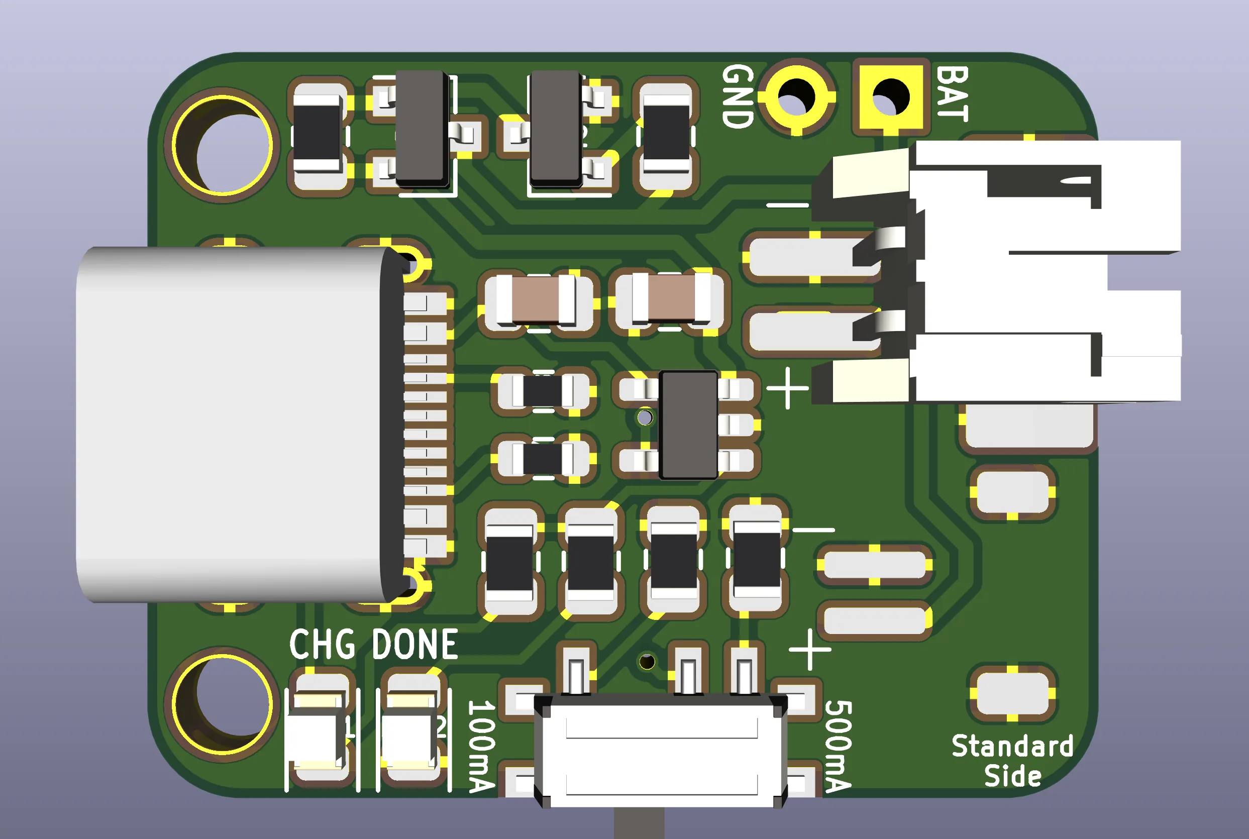
The schematic and PCB layout of the new design can be seen below.
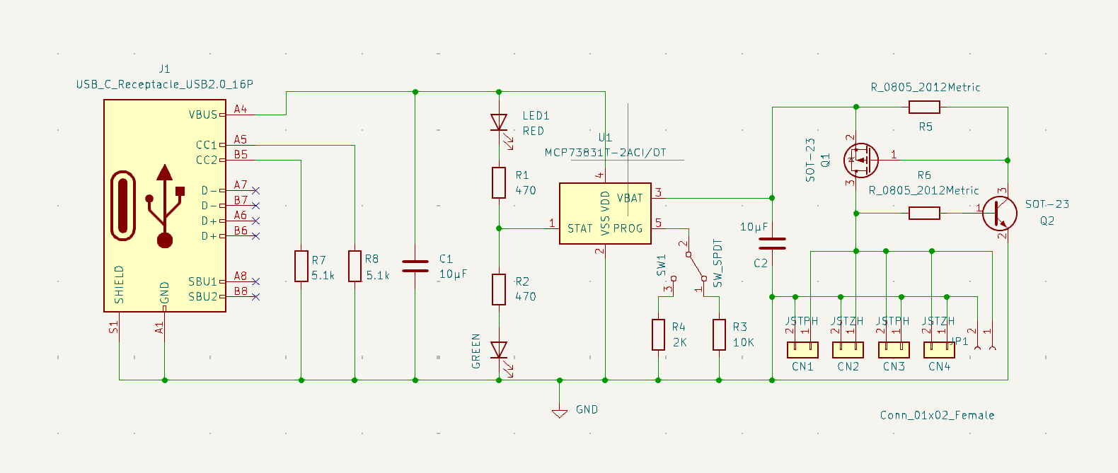
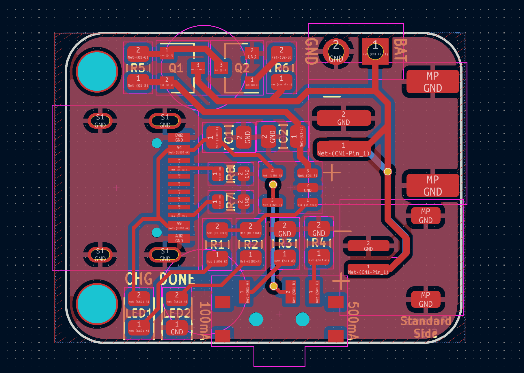
You can find the files for both the previous version, and the new version, in our GitHub repository.

LiPo Charger
A LiPo battery charger based on the Adafruit MicroLipo, with added reverse polarity protection.
Assembly Instructions
To build one of these for yourself, you’ll need the following components:
| Component: | Location: |
|---|---|
| 1x LiPo Charger Board | |
| 1x 16 pin USB type C Connector | J1 |
| 2x JST-PH connector | CN1/3 |
| 2x JST-ZH connector (optional) | CN2/4 |
| 1x MCP73831/2 SOT23 Charging IC | U1 |
| 2x 0805 470Ω Resistors | R1/R2 |
| 1x 0805 10kΩ Resistor | R3 |
| 1x 0805 2kΩ Resistor | R4 |
| 1x 0805 100kΩ Resistor | R5 |
| 1x 0805 1MΩ Resistor | R6 |
| 2x 0805 5.1kΩ Resistors | R7/8 |
| 2x 0805 10uF Capacitors | C1/2 |
| 1x P Channel MOSFET transistor | Q1 |
| 1x SOT23 BJT NPN Transistor | Q2 |
| 2x 0805 LEDs, colours optional | LED1/2 |
You can forego some of the JST connectors, depending on the outputs you wish to have on the board. You can also exclude them entirely, and solder wires to the PCB to attach them to other connectors/batteries.
If you want to alter the charging speeds, you can substitute R4 and R5 with different values. The default resistors allow switching between 100 and 500mA charging speeds, which should be suitable for most batteries.
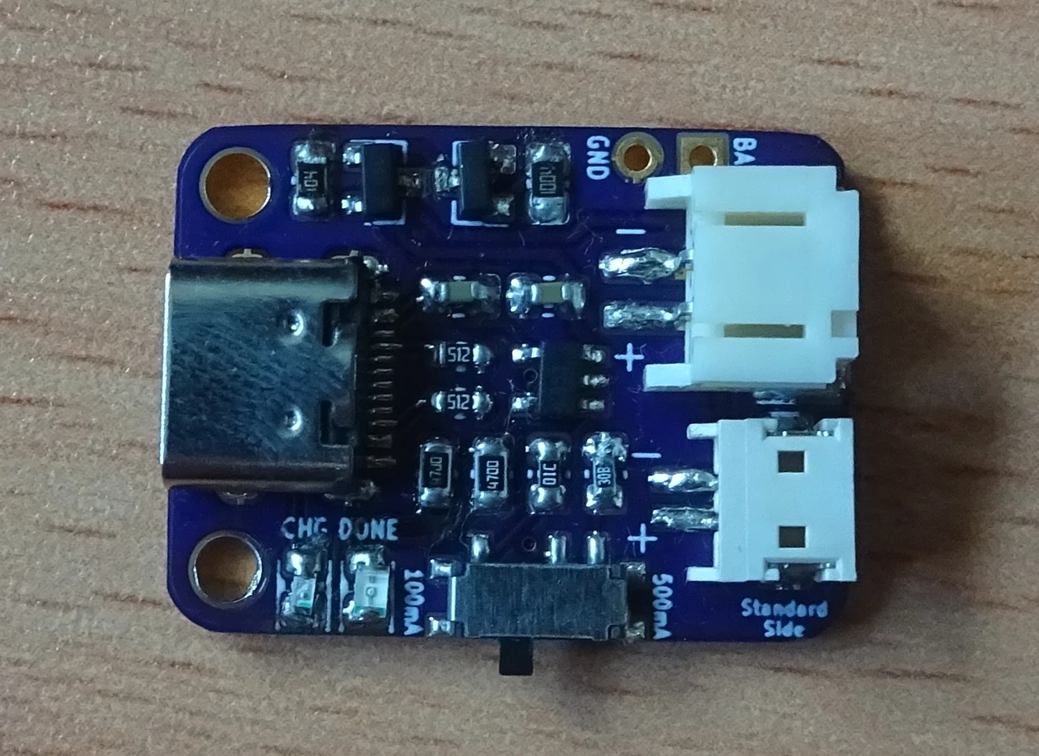

The board pictured was soldered by hand – easy to do if you’re an experienced solderer. We’d recommend leaving the JST connectors until last, as they will block access to nearby components.
If you’re struggling to solder one by hand, some low temperature solder paste along with a hot plate might prove an easier alternative.
Where To Get One
You can find the files needed to create one of these for yourself on GitHub, using the link below.
LiPo Charger
A LiPo battery charger based on the Adafruit MicroLipo, with added reverse polarity protection.
We use OSH Park to have the PCB manufactured. If you’re just looking to order the PCB, you can order the board from OSH Park using following link.

LiPo Charger Type C v1.0
Order the USB type C LiPo charger PCBs from OSH Park
There are also services available to have the board assembled for you, though we cannot recommend any as we have never used one. Provide them the files found on GitHub, and they should be able to get you started.


